RC Car monitoring and race follow-up
Intend
-
- Battery Temperature
- Engine Rpm
-
- Lap count
- Average time/lap + trend
- Average motor cycle per lap + trend (tend to evaluate efficiency by evaluating slipping)
- Posiiton amongst the competitors
Tech Doc
Blog
Manual lap count is a good start
To count lap, the initial idea was to use something like this Dog Fence with Ardiuno.
I bought the electronic component need to test the approach and made it working with Arduino but could not make it working with the moteino. Probably 3.3V related. I sent a mail to the author who responded that a solution would be to have two loops but I also realised that passing too quicky over the loop will fail the read….dead end for the moment. Turns out that the systems that are actually ont he market use either infrared detection or an directional antenna made out of a wire loop under the ground. My knowledge in the area are quite limited so I will start with a manual lap count : the driver would have to press a button on his remote to report the lap. Not ok for competition but probably ok for personal lap tracking. After all, all I want is to know my own performances.
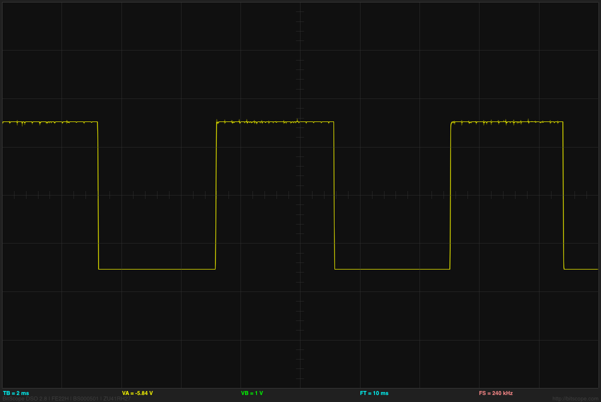
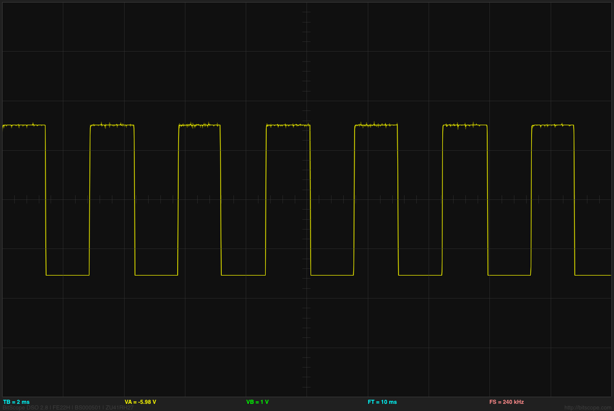
So, the plan is to connect the moteino on AUX1 (on the receiver) and to detect the signal sent by the remote. Damn I love this oscilloscope… apparently, it is just a matter of how long os the squared high, 3300µs when released, 4400µs when pressed. Houra.. my moteino can do that as well.
Monitoring motor speed
The initial idea was to connect moteino's digital input on the three wire connecting the motor to the speed controller. Then, because I sensed that the community of rc drivers were reluctant to the idea of interfering with the precious signal coming from the expensive controller, I though that the “sensored” connector might be a good option.
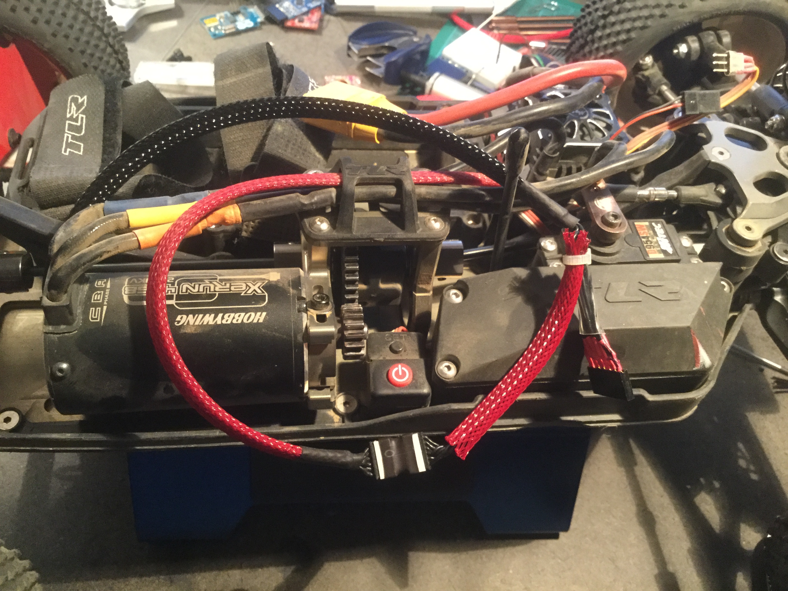
Looking at its specification, I realised that not only I could get the same result but also that the controller powers to PCB inside the motor with 5V (just what we need to power the moteino) but also that the motor was equipped with a small thermistor that I could use to read motor temperature.
Connecting the oscilloscope to wires 2, 3 and 4 showed three beautiful digital signals send by the three HAL sensors inside the motor.
A bit of wiring later, the moteino was mounted on the “sensored” line. I used the PinChangedInterupt library to detect the square signals on each wires and calculate the RPM. I used interrupt to make sure I dont miss a signal while sending over the RFM69. When pushed to the max, the motor shows 120000 RPM which I divided by two to obtain the 60000RPM that I expect considering the 4S and the 2250kvm motor but I should investigate further more to understand exactly why. I guess rotating the axe of the motor manually and see which HAL sensor turn low and when will help.